Overview Of Electrical Mep Systems in Commercial Buildings
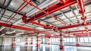
Electrical MEP systems are a critical component of commercial buildings, supporting all operational, safety, and functional requirements. Unlike residential projects, commercial buildings operate under higher electrical loads, longer operating hours, and stricter regulatory controls. Electrical MEP systems must be designed to function continuously and safely while accommodating a wide range of equipment, occupancy patterns, and future expansions. In commercial developments such as offices, shopping centers, hospitals, hotels, and mixed-use buildings, electrical systems serve lighting, power distribution, HVAC equipment, fire protection systems, elevators, data networks, security systems, and building management systems. Failure in any part of the electrical infrastructure can directly impact safety, business continuity, and asset protection. Electrical MEP systems must therefore be approached as a coordinated engineering discipline rather than an isolated technical task.
Role of Electrical Design in Commercial Projects
The electrical design establishes how power enters the building, how it is distributed, protected, controlled, and maintained throughout its life cycle. Electrical MEP engineers are responsible for transforming project requirements into practical, buildable solutions. This includes selecting appropriate system voltages, defining distribution strategies, allocating electrical rooms, and coordinating routes for cables and containment systems. A well-planned design ensures:
- Safe power distribution to all areas
- Reliable operation under normal and emergency conditions
- Compliance with statutory and safety regulations
- Ease of installation and maintenance
- Flexibility for future load growth
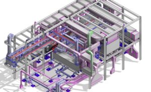
Electrical MEP Coordination and Site Integration
Coordination with architectural, structural, mechanical, and plumbing systems is essential in commercial projects. Electrical MEP systems share limited space with HVAC ducts, plumbing pipes, fire fighting lines, and structural elements. Poor coordination can result in clashes, rework, and unsafe installations. Early coordination during the design stage reduces site conflicts and ensures smooth execution during construction. Effective coordination focuses on:
- Electrical room locations and access
- Vertical and horizontal service routes
- Clearances around panels and equipment
- Segregation of power, data, and fire alarm systems
Electrical Design Stages in Commercial Projects
Electrical MEP systems typically progresses through the following stages:
Concept Design: Defines system philosophy, utility connection requirements, and major equipment locations. Schematic Design: Establishes preliminary layouts, load estimates, and distribution concepts. Detailed Design: Includes final load calculations, cable sizing, panel schedules, and coordinated drawings. Construction Documentation: Provides approved drawings and technical specifications for installation. Construction Support: Includes responding to site queries, reviewing shop drawings, and resolving coordination issues. Testing and Commissioning: Ensures installed systems operate safely and as intended. Each stage must consider site conditions and constructability to avoid delays and cost overruns.
Electrical Codes and Design Standards
Electrical systems must comply with recognized international and local standards to ensure safety and performance. These standards govern cable sizing, protection systems, earthing, emergency power, and fire safety requirements. Designers must always apply the latest applicable standards and confirm local authority requirements before finalizing designs. Key objectives of electrical codes include:
- Protection against electric shock
- Prevention of fire hazards
- Equipment, safety and durability
- Standardization of design practices
Local Authority and Approval Requirements
Every commercial project requires approvals from relevant authorities. Electrical submissions typically include load schedules, single line diagrams, layout drawings, and equipment specifications. Authorities may also inspect installations before energization. Electrical designers must understand submission procedures, inspection stages, and documentation requirements specific to the project location. Failure to meet approval requirements can lead to:
- Project delays
- Costly modifications
- Rejection of installations
Electrical Safety Philosophy
Safety is the primary objective of electrical MEP design. Commercial buildings pose higher risks due to large occupancy, complex systems, and continuous operation. Design decisions must always prioritize personnel safety over cost or convenience. Key safety considerations include:
- Proper earthing and bonding
- Short circuits and overload protection
- Fire-resistant cable systems where required
- Emergency power availability
- Safe access for operation and maintenance
Electrical Drawings and Documentation
Clear documentation is essential for accurate installation and long-term maintenance. Well-prepared drawings reduce site confusion and improve installation quality. Typical electrical MEP design deliverables include:
- Power and lighting layout drawings
- Single line diagrams
- Panel schedules
- Load calculation sheets
- Earthing and lightning protection layouts
- Technical specifications
Responsibilities of Electrical Engineers on Site
Electrical MEP engineers play an active role throughout construction. Site involvement ensures that design assumptions align with actual installation conditions. Their responsibilities include:
- Clarifying design intent to contractors
- Reviewing shop drawings and material submittals
- Resolving site coordination issues
- Supporting inspections and testing
- Assisting during commissioning and handover
Common Site Challenges and Practical Solutions
Common challenges in commercial electrical projects include limited space, late design changes, coordination conflicts, and unrealistic construction timelines. Practical solutions involve early planning, regular coordination meetings, and clear communication between all stakeholders. Adopting proven installation practices, maintaining safety standards, and documenting changes properly contribute to successful project delive.
Electrical Load Analysis and Power Distribution Design
Importance of Load Analysis in Commercial Buildings
Electrical load analysis is the foundation of every commercial electrical design. All downstream decisions—such as transformer sizing, generator capacity, cable sizing, panel ratings, and space allocation—depend on accurate load assessment. Errors at this stage often lead to overloaded systems, nuisance tripping, voltage drops, overheating, or costly upgrades after project completion. Commercial buildings have diverse load profiles due to offices, retail areas, HVAC systems, elevators, kitchens, IT equipment, and life safety systems operating simultaneously. Load analysis must therefore consider actual usage patterns rather than relying solely on connected loads shown on drawings. A well-prepared load analysis ensures:
- Safe and reliable system operation
- Compliance with utility and authority requirements
- Optimized equipment size
- Reduced operational and maintenance issues
Classification of Electrical Loads
Electrical loads in commercial buildings are typically classified to facilitate proper design and protection.
Lighting Loads: Includes internal lighting, external lighting, decorative lighting, and emergency lighting. Lighting loads are generally continuous loads and must be calculated accordingly. Power Loads: Includes socket outlets, office equipment, pantry appliances, and small machinery. These loads vary based on occupancy and usage patterns. Mechanical Loads: Includes HVAC equipment such as chillers, air handling units, fan coil units, exhaust fans, pumps, and cooling towers. These are often the largest electrical loads in commercial buildings. Special Loads: Includes elevators, escalators, data centres, medical equipment, kitchens, and specialized systems. Life Safety Loads: Includes fire alarm systems, emergency lighting, smoke extraction fans, fire pumps, and essential services connected to emergency power. Proper load classification helps in segregation, protection coordination, and emergency power planning.
Connected Load vs Demand Load
Connected Load: The connected load is the total rated power of all electrical equipment connected to the system. It represents the maximum possible load if all equipment operates simultaneously.
Demand Load: The demand load represents the actual expected load during normal operation, considering diversity and usage patterns. Demand load is always lower than connected load and is used for system sizing. Designing based only on connected load leads to oversized systems, increased costs, and inefficient operation.
Demand and Diversity Factors
Demand Factor: The ratio of maximum demand to connected load. It reflects how much of the connected load is expected to operate simultaneously.
Diversity Factor: Accounts for the fact that not all loads operate at peak capacity at the same time, especially across different areas or tenants. Applying realistic demand and diversity factors is critical in commercial projects, especially in office buildings, shopping malls, and mixed-use developments. Typical considerations include:
- Occupancy type
- Operating hours
- Equipment usage patterns
- Historical data from similar projects
Load Calculation Methodology
Load schedules should be updated regularly as design evolves to reflect changes in equipment and layouts. So, Calculations should follow a structured and documented approach:
- Identify all electrical equipment and systems
- Determine rated power and operating characteristics
- Apply demand and diverse factors
- Separate normal and emergency loads
- Include future load allowances
- Summarize loads at panel, distribution board, and transformer levels
Allowance for Future Expansion
Commercial buildings often undergo changes in tenancy, usage, and technology. Electrical designs must include provisions for future growth. Failure to consider future expansion often results in disruptive and expensive retrofits. Therefore, Common practices include:
- Spare capacity in transformers and generators
- Space for additional panels
- Spare breakers in distribution boards
- Oversized cable trays where feasible
Utility Power Supply Considerations
Utility constraints can significantly influence system design, including transformer selection, substation layout, and backup power requirements. Electrical designers must coordinate early with the utility provider to determine:
- Available supply voltage
- Maximum allowable load
- Connection method
- Metering requirements
High Voltage (HV) and Low Voltage (LV) Distribution Systems
Large commercial buildings may receive power at high voltage levels, which is then stepped down through transformers.
High Voltage Systems: Used for bulk power supply, offering reduced losses and improved efficiency.
Low Voltage Systems: Used for internal building distribution to panels, equipment, and outlets. Design decisions must consider safety, space availability, maintenance access, and authority requirements.
Power Distribution Philosophy
Distribution philosophy must also consider tenant metering, emergency power segregation, and operational flexibility. Power distribution must ensure reliability, selectivity, and ease of maintenance. Common distribution approaches include:
- Centralized distribution
- Decentralized floor-wise distribution
- Dedicated distribution for critical loads
Single Line Diagrams (SLD)
Single Line Diagrams are the backbone of electrical documentation. SLDs are used by designers, contractors, authorities, and maintenance teams and must be clear, accurate, and updated. They provide a simplified representation of the entire electrical system, showing:
- Power sources
- Transformers
- Panels and feeders
- Protection devices
- Metering points
Voltage Drop Considerations
Excessive voltage drop can cause equipment malfunction, reduced efficiency, and overheating. Designs should limit voltage drop within acceptable limits from source to final point of use. Voltage drop calculations must consider:
- Cable length
- Load current
- Cable size
- Power factor
Short-Circuit Level and System Rating
Short-circuit calculations determine the maximum fault current at various points in the system. Equipment such as breakers, panels, and switchgear must be rated to safely withstand and interrupt these currents. Failure to account for short-circuit levels can lead to catastrophic equipment failure and safety hazards.
Coordination with Emergency Power Systems
This segregation ensures proper sizing of generators, UPS systems, and automatic transfer schemes. Only critical systems should be connected to emergency power to optimize system capacity and cost. Load analysis must clearly separate:
- Normal loads
- Essential loads
- Life safety loads
Site Execution Considerations
During construction, load assumptions must be verified against actual installed equipment. Electrical engineers must review site changes and update load calculations accordingly to maintain system integrity. Common site issues include:
- Equipment rating changes
- Additional tenant requirements
- Temporary power demands
Best Practical Practices
- Always maintain updated load schedules
- Avoid excessive oversizing
- Verify equipment ratings during procurement
- Coordinate early with utilities and authorities
- Plan for realistic future growth
These practices reduce risks and improve long-term performance.
Substations, Transformers, and Low Voltage Systems
Role of Substations in Commercial Buildings
Electrical substations form the primary interface between the utility power supply and the building’s internal electrical distribution system. In commercial buildings with high electrical demand, substations are essential for stepping down utility voltage levels to usable low voltage while ensuring safety, reliability, and control. Poor substation planning can result in restricted access, overheating, unsafe working conditions, and rejection by authorities. A properly designed substation ensures:
- Safe transformation and distribution of power
- Compliance with utility and authority requirements
- Adequate capacity for present and future loads
- Ease of operation, maintenance, and emergency access
Types of Substations Used in Commercial Projects
Substation configuration depends on utility requirements, building size, and load magnitude.
Indoor Substations: Installed within dedicated electrical rooms. Common in high-rise and mixed-use buildings where outdoor space is limited. Outdoor Substations: Used where space permits and utility regulations allow. Often simpler to ventilate and maintain. Package Substations: Prefabricated units containing transformers and switchgear. Frequently used for fast-tracking commercial developments. Each type requires compliance with safety clearances, fire separation, and access requirements.
Location Planning for Substations
Substation location has a major impact on project execution and long-term operation. Substations should never be located below flood-prone areas or directly beneath water services without proper protection. Key site considerations include:
- Direct access for utility and maintenance personnel
- Proximity to main load centres
- Structural capacity for heavy equipment
- Ventilation and heat dissipation
- Fire separation from occupied areas
Transformer Fundamentals
Transformers reduce high voltage supply to low voltage levels suitable for building distribution. They are among the most critical and expensive components of electrical systems. Transformers must be sized accurately based on demand load, not merely connected load. Transformer selection affects:
- System efficiency
- Energy losses
- Noise levels
- Heat generation
- Maintenance requirements
Types of Transformers Used in Commercial Buildings
Oil-Filled Transformers: Offer high efficiency and overload capability but require strict fire protection and oil containment measures.
Dry-Type Transformers: Commonly used in indoor substations due to reduced fire risk and simpler installation.
Cast Resin Transformers: Used where higher safety and moisture resistance are required. Selection depends on fire regulations, space availability, and operational priorities.
Transformer Sizing and Capacity Planning
Oversizing increases capital cost and losses, while under sizing leads to overheating and premature failure. A balanced approach ensures reliable operation and energy efficiency. Transformer sizing must consider:
- Maximum demand load
- Diversity factors
- Future expansion allowance
- Harmonic content
- Ambient temperature
Transformer Installation Requirements
Site installation must comply with manufacturer recommendations and authority guidelines. Transformers should be installed on vibration-isolated foundations to reduce noise transmission. Important installation aspects include:
- Minimum clearance from walls and equipment
- Adequate ventilation openings
- Noise control measures
- Fire-rated enclosures where required
- Proper earthing connections
Low Voltage (LV) Distribution Systems Overview
Low voltage systems distribute power from transformers to final loads through panels, switchboards, and feeders. LV systems must ensure safety, selectivity, and continuity of supply. LV distribution design directly affects operational reliability. Key objectives include:
- Controlled fault isolation
- Ease of maintenance
- Safe operation under fault conditions
Main Low Voltage Switchboards
Main LV switchboards receive power from transformers and distribute it to downstream panels. Switchboards must be accessible, well-ventilated, and clearly labelled. Design considerations include:
- Incoming and outgoing feeder ratings
- Short-circuit withstand capacity
- Protection coordination
- Metering and monitoring provisions
- Space for future feeders
Switchgear and Protection Devices
Protection devices safeguard electrical systems from faults and overloads. Protection coordination ensures that only the faulty section is isolated during a fault, minimizing disruption. Common devices include:
- Air circuit breakers (ACB)
- Molded case circuit breakers (MCCB)
- Miniature circuit breakers (MCB)
- Residual current devices (RCD)
Distribution Boards and Panel Design
Distribution boards divide power into smaller circuits serving lighting, power outlets, and equipment. Panels should be installed in accessible locations with sufficient working clearance. Panel design must consider:
- Load balancing across phases
- Circuit segregation
- Spare capacity
- Clear identification and labelling
Motor Control Centers (MCCs)
MCCs supply and control large mechanical loads such as pumps, fans, and HVAC equipment. Coordination with mechanical engineers is essential for MCC design. Design requirements include:
- Appropriate starter types
- Protection against overload and short-circuit
- Interface with control and automation systems
- Clear access for operation and maintenance
Panel Schedules and Documentation
Panel schedules summarize circuit details, breaker ratings, cable sizes, and connected loads. Schedules must be updated to reflect site changes. Accurate schedules help:
- Contractors during installation
- Inspectors during approvals
- Facility teams during operation
Safety and Maintenance Considerations
Electrical rooms and panels must be designed for safe access and maintenance. Safe design reduces operational risk and ensures compliance with safety regulations. Key safety requirements include:
- Adequate working clearances
- Proper lighting and ventilation
- Lockable enclosures
- Clear warning signage
Common Site Issues and Practical Solutions
Typical site challenges include space constraints, late equipment changes, and coordination conflicts. Attention to these factors improves construction quality and long-term reliability. Practical solutions involve:
- Early substation layout finalization
- Coordination workshops with all disciplines
- Maintaining spare capacity and access routes
Lighting, Emergency Power, and Life Safety Systems
Importance of Lighting Design in Commercial Buildings
Lighting is one of the most visible and critical electrical systems in any commercial building. Proper lighting not only ensures functional illumination for tasks and movement but also affects safety, energy efficiency, and occupant comfort. Poor lighting can lead to reduced productivity, unsafe conditions, and increased energy costs. Lighting systems are also closely linked with occupancy patterns, HVAC control, and building management systems. Commercial lighting designs must consider:
- Functional requirements (offices, retail, lobbies, corridors)
- Architectural and aesthetic integration
- Energy efficiency and sustainability
- Emergency lighting for life safety
Types of Lighting Systems
General Lighting: Provides uniform illumination across spaces like offices, corridors, and conference rooms. Usually includes fluorescent, LED, or troffer fixtures.
Task Lighting: Provides localized illumination for specific tasks such as workstations, kitchens, or reception areas. Accent and Decorative Lighting: Highlights architectural features, products, or displays in commercial areas. Emergency Lighting: Ensures safe egress in case of power failure. Must comply with authority regulations.
Lighting Load Calculation and Layouts
Layouts should avoid shadows, glare, or dark spots, and consider maintenance access for lamps and controls. Lighting load calculation involves:
- Identifying fixture types and ratings
- Determining required lux levels for different areas
- Applying diversity and usage factors
- Preparing lighting layout drawings
Energy Efficiency in Lighting
Modern commercial projects focus on energy-efficient lighting to reduce operational costs. Energy efficiency measures also support sustainability certifications like LEED or local energy codes. Strategies include:
- LED fixtures with high efficacy
- Occupancy sensors and daylight dimming
- Zoned lighting control
- Proper selection of luminaires for ceiling height and space
Emergency Power Systems Overview
Emergency power ensures critical systems remain operational during utility outages. Effective emergency power design minimizes risk to life and property. In commercial buildings, emergency power supports:
- Fire alarm and smoke extraction systems
- Emergency lighting and exit signage
- Life safety elevators
- Security and communication systems
- Critical IT loads in data centres
Generators and Backup Power Planning
It provide backup power when utility supply is interrupted. Generators are typically installed in dedicated rooms or outdoor enclosures with ventilation, fire protection, and noise mitigation. Key considerations:
- Correct sizing based on critical loads
- Fuel type and storage capacity
- Automatic Transfer Switch (ATS) integration
- Maintenance access and safety clearances
Uninterruptible Power Supply (UPS) Systems
UPS systems protect sensitive equipment from short-term power interruptions and voltage fluctuations. They are critical for:
- Data centres
- Security systems
- Communication equipment
- Design considerations include:
- Load capacity
- Runtime requirements
- Battery placement and ventilation
- Integration with generator systems for long-duration outages
Automatic Transfer Switch (ATS) Integration
ATS ensures seamless transfer of power between utility and emergency sources. ATS reliability is essential to maintain life safety and operational continuity. Proper ATS design involves:
- Correct sizing to handle maximum load
- Coordination with generator and UPS systems
- Fail-safe operation and maintenance accessibility
- Monitoring and alarm integration
Fire Alarm and Life Safety Systems
Fire alarm and life safety systems are mandatory in commercial buildings. Electrical design for these systems must comply with codes and integrate with emergency power sources. Electrical engineers must ensure proper circuit segregation, emergency supply, and clear labelling for maintenance. Components include:
- Smoke and heat detectors
- Fire alarm control panels
- Manual call points
- Sounders and strobes
- Fire pumps and sprinkler system interfaces
Emergency Lighting and Exit Signage
Emergency lighting and exit signage guide occupants safely during power failures. Proper installation ensures compliance with local codes and maximizes occupant safety. Requirements include:
- Illuminated exit signs
- Emergency luminaires along corridors, stairs, and exits
- Connection to dedicated emergency circuits with battery backup or generator supply
- Regular testing and maintenance
Coordination with Other MEP Systems
Early coordination prevents clashes, reduces rework, and ensures functional integration. Lighting and emergency systems must be coordinated with:
- HVAC equipment to avoid conflicts with diffusers and ducts
- Plumbing and fire protection piping
- Architectural finishes and ceiling layouts
Site Installation Considerations
Regular site inspections and coordination meetings ensure design intent is maintained. During construction, practical challenges often arise:
- Maintaining cable segregation for emergency and normal circuits
- Routing conduits in congested ceilings
- Access for maintenance and lamp replacement
- Correct labelling and commissioning of panels and circuits
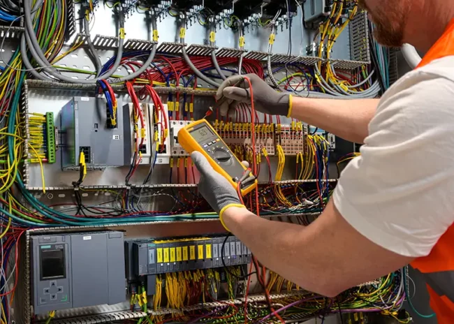
Testing, Commissioning, and Maintenance
Proper commissioning guarantees operational readiness and long-term reliability. Testing and commissioning include:
- Functional testing of lighting circuits
- Verification of emergency power operation
- Load testing for generators and UPS
- Fire alarm system functional tests
- Documentation of test results
Practical Best Practices
- Segregate life safety and normal power circuits
- Ensure adequate working clearances around panels and luminaires
- Include spare capacity for future load increases
- Document all system changes during construction
- Coordinate installation with other trades to prevent clashes
Following these practices ensures safety, reliability, and ease of operation throughout the building’s lifecycle.
Earthing, Lightning Protection, Cabling, and Infrastructure
Importance of Earthing in Commercial Buildings
Earthing (or grounding) is critical for the safety and reliability of electrical systems. It provides a low-resistance path for fault currents, stabilizes voltage during transient conditions, and ensures the safe operation of protection devices. Proper earthing prevents electric shocks, equipment damage, and fire hazards. In commercial projects, earthing systems must support:
- Power distribution systems
- Lighting systems
- Emergency and life safety systems
- Sensitive IT and communication equipment
Types of Earthing Systems
Common earthing systems include:
TT System: Earth electrode at the building, separate from the utility earth. Often used where utility earth is unreliable. TN-S System: Separate neutral and protective conductor throughout the building. Common in commercial and industrial buildings. TN-C-S System: Combined neutral and protective conductor at the supply, separated inside the building. Widely used for high-rise buildings. IT System: Isolated or high-resistance grounded system, used for critical loads like data centres and hospitals. Selection depends on utility supply, building type, and safety requirements.
Earthing Components and Design Considerations
Key components include:
- Earthing electrodes (rods, plates, or mats)
- Earthing conductors
- Main earthing busbars
- Bonding connections to panels, transformers, and metallic structures
- Design considerations:
- Low ground resistance (typically <5 ohms)
- Corrosion-resistant materials (copper or galvanized steel)
- Adequate spacing of electrodes
- Periodic testing and maintenance
Lightning Protection Systems
Lightning poses a serious risk to commercial buildings, particularly high-rise structures. A lightning protection system (LPS) safely intercepts and diverts lightning strikes to ground.
LPS components include:
- Air terminals (rods)
- Down conductors
- Grounding network
- Surge protection devices
Installation considerations:
- Avoid interference with other services
- Maintain adequate clearances from sensitive equipment
- Ensure connection with building earthing system
Surge Protection and Transient Voltage Suppression
Lightning and switching events can produce voltage surges that damage equipment. SPDs are installed at main distribution panels and critical branch panels. Surge protection devices (SPDs) safeguard:
- Electrical panels
- UPS and generator systems
- IT and communication networks
Cable Sizing Principles
Correct cable sizing ensures safe operation, minimizes voltage drop, and prevents overheating. Oversized cables increase cost, while undersized cables risk failure and hazards. Factors considered include:
- Load current
- Length of run
- Ambient temperature and installation conditions
- Voltage drops limitations
- Short-circuit withstand capacity
Cable Routing and Containment Systems
Efficient cable routing is essential for safety, maintenance, and compliance. Common methods:
- Cable trays
- Conduits
- Ducts and sleeves
Practical considerations:
- Separate power, data, and fire alarm cables
- Avoid sharp bends and congested paths
- Provide supports at recommended intervals
- Maintain accessibility for maintenance and future expansion
Electrical Room Design and Layout
Electrical rooms house transformers, panels, switchgear, and UPS systems. Proper layout is critical for safe installation and operation.
Key requirements:
- Adequate space and clearances per code
- Ventilation and cooling for heat-generating equipment
- Access routes for installation and maintenance
- Fire-rated walls and doors where required
- Signage and safety instructions
Cable Terminations and Labelling
Proper terminations and labelling reduce installation errors and simplify maintenance. Best practices:
- Use high-quality connectors and lugs
- Torque connections according to manufacturer instructions
- Clearly label all cables, panels, and circuits
- Document as-built changes for handover
Coordination with Other Trades
Early coordination prevents clashes and costly modifications during installation. Cabling and containment must be coordinated with:
- HVAC ducts
- Plumbing pipes
- Fire protection lines
- Architectural ceilings and partitions
Safety and Maintenance Considerations
- Maintain adequate working clearance around panels and trays
- Avoid overcrowding of conduits and cable trays
- Protect cables from mechanical damage
- Periodically inspect earthing and lightning systems
Safe installation and maintenance practices reduce hazards and extend equipment life.
Practical Best Practices
- Design earthing and lightning systems together for integrated protection
- Maintain segregation of power, data, and fire alarm cables
- Use high-quality materials for long-term reliability
- Allow spare capacity for future loads
- Document cable routes, terminations, and earthing layouts
Following these practices ensures compliance, safety, and operational efficiency on site.
Energy Efficiency, Coordination, Commissioning & Maintenance
Importance of Energy Efficiency in Commercial Buildings
Energy efficiency is a critical component of modern electrical MEP design. Commercial buildings often have large, continuous electrical loads due to lighting, HVAC, elevators, and IT systems. Reducing energy consumption not only lowers operational costs but also supports sustainability initiatives and compliance with energy regulations. Key benefits of energy-efficient electrical systems include:
- Lower utility costs
- Reduced heat generation and cooling load
- Extended equipment life
- Compliance with local energy codes and green building certifications
- Improved occupant comfort and satisfaction
Strategies for Energy-Efficient Electrical MEP Systems
Efficient Lighting
- Use LED lighting with high efficacy
- Incorporate occupancy sensors and daylight dimming
- Apply zoning for selective lighting control
Optimized Power Distribution
- Minimize transformer and panel losses
- Use proper cable sizing to reduce resistive losses
- Implement power factor correction for inductive loads
Integration with Building Management Systems (BMS)
- Monitor energy consumption
- Control lighting, HVAC, and pumps efficiently
- Generate alerts for abnormal conditions
Use of Renewable Energy
- Solar panels for auxiliary loads
- Integration with grid-tied systems for cost savings
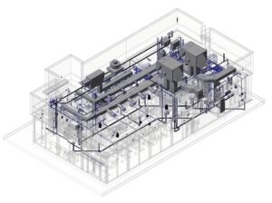
Coordination of Electrical MEP with Other MEP Disciplines
Electrical systems are tightly interlinked with mechanical, plumbing, and fire protection systems. Proper coordination avoids installation conflicts, reduces rework, and ensures smooth operations.
Key coordination points include:
- Cable tray and conduit routes versus HVAC ducts and piping
- Panel and MCC locations relative to structural elements
- Emergency and life safety system integration with fire protection
- Space allocation for maintenance access
Coordination meetings and clash detection sessions during design and construction phases are essential for error-free implementation.
Testing and Commissioning
Commissioning verifies that all electrical systems are installed correctly, operate safely, and meet design requirements. It includes:
Pre-Commissioning Checks
- Verify equipment ratings, connections, and earthing
- Inspect cables, panels, and protective devices
- Ensure clearances and working spaces
Functional Testing
- Test normal and emergency power operation
- Verify lighting, UPS, and generator performance
- Check fire alarm, life safety, and communication systems
Documentation
- Record test results, observations, and deviations
- Prepare as-built drawings for handover
Proper commissioning ensures reliability, safety, and compliance with standards.
Load Testing and Power Quality Verification
Load testing and power quality checks validate system performance under real operating conditions.
Key activities include:
- Testing transformer and panel load distribution
- Checking voltage drops and harmonic levels
- Measuring neutral currents and power factor
- Verifying generator and UPS response times
Identifying issues during commissioning allows timely corrections before handover.
Maintenance Planning and Practices
Regular maintenance ensures long-term reliability and prevents unexpected downtime. Essential practices include:
Preventive Maintenance
- Inspect and clean switchgear, panels, and transformers
- Test circuit breakers, relays, and protective devices
- Check earthing and bonding systems
Corrective Maintenance
- Respond promptly to faults or abnormal readings
- Replace worn or defective components
Documentation and Scheduling
- Maintain logs of inspections, tests, and maintenance activities
- Plan periodic reviews for high-load equipment
A structured maintenance program reduces operational risks and extends equipment life.
Energy Monitoring and Management
Implementing an energy monitoring system helps track consumption, detect inefficiencies, and plan load management. Integration with BMS allows real-time control and proactive maintenance alerts. Effective strategies include:
- Installing sub-metering at major loads
- Monitoring HVAC, lighting, and critical systems separately
- Identifying peak demand periods for load shifting
- Using data to optimize operations and reduce energy bills
Practical On-Site Energy Efficiency Measures
- Optimize cable routing and sizing to reduce losses
- Use LED lighting and occupancy controls
- Implement load shedding strategies during peak hours
- Schedule HVAC and pumps based on occupancy and operating hours
- Ensure generator and UPS efficiency during testing and operation
These measures are highly practical for on-site implementation and provide immediate operational benefits.
Safety, Compliance, and Operational Best Practices
- Maintain proper working clearances and access for all equipment
- Ensure protective devices and earthing systems are fully functional
- Document system changes, upgrades, and expansions
- Train facility teams on safe operation and emergency procedures
- Conduct regular site inspections to verify compliance with codes
Safety, operational reliability, and compliance are non-negotiable aspects of successful commercial electrical systems.
Future-Proofing Electrical MEP Systems
Commercial buildings often undergo tenant changes, technology upgrades, or expansion. Futureproofing reduces retrofit costs and avoids operational disruptions. Designing for future adaptability includes:
- Spare capacity in panels, transformers, and cables
- Allocating space for additional switchgear and conduits
- Flexible routing of cable trays and containment systems
- Modular UPS and emergency power arrangements
Summary of Key Practical Guidelines for Electrical MEP
- Energy efficiency reduces operational costs and enhances sustainability
- Coordination with all MEP disciplines prevents site clashes
- Comprehensive testing and commissioning verify performance and safety
- Structured maintenance ensures long-term reliability
- Futureproofing
- accommodates expansion and technological upgrades
Practical implementation of these guidelines guarantees a safe, efficient, and reliable electrical system for commercial buildings.