When engineers and building owners think about lightning protection. They often focus the conversation on air termination networks, down conductors, and earthing systems.They rarely give enough attention to the documentation that guides engineers in designing, coordinating, and maintaining these systems alongside the rest of a building’s critical infrastructure. Yet regulators and life-safety standards assign it equal weight. Incomplete or poorly prepared lightning protection documentation does not simply create a compliance gap. It introduces a silent hazard that physically obstructs emergency egress corridors, electrically disrupts fire alarm panels, and corrupts the signals of smoke detectors and emergency lighting circuits at precisely the moment these systems matter most.
At Varow International, Pakistan’s leading MEP consultants with over four decades of experience in electrical, fire fighting, and fire and life safety services. We understand that lightning protection is never an isolated discipline. Engineers must coordinate, document, and review it in relation to every other building system — particularly fire safety and emergency access. This coordination must run from the earliest design stage through to final handover and ongoing maintenance. This article explains exactly how comprehensive lightning protection documentation achieves that coordination and why it matters for every commercial, industrial, and high-rise building in Pakistan.
Understanding the Scope of Lightning Protection Documentation
What Lightning Protection Documentation Actually Covers
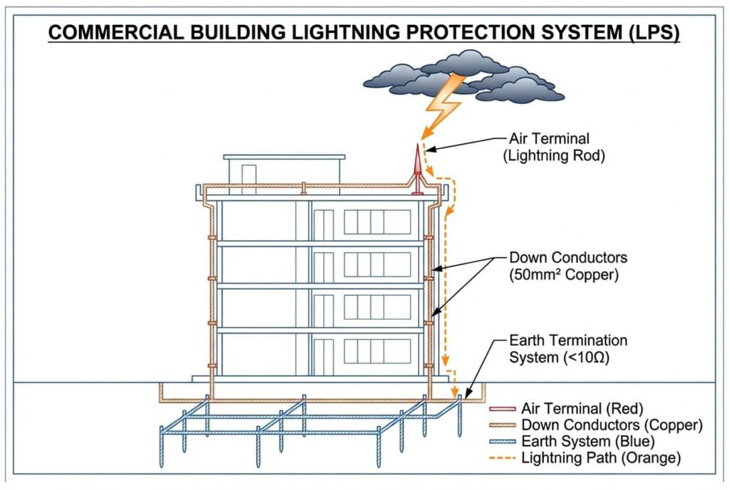
Lightning protection documentation is far more than a set of installation drawings submitted for authority approval. In its complete form, it encompasses a risk assessment report prepared in accordance with IEC 62305-2 or BS EN 62305-2, which calculates the probability and consequence of a lightning strike to determine the required level of protection. It includes design drawings that show the exact routing of down conductors, the location of test joints, the layout of the earth electrode system, and the position of every air termination rod or mesh conductor on the roof.
Beyond drawings, thorough documentation includes a coordination matrix that maps the relationship between the lightning protection system and every other MEP system in the building. It contains inspection and test records, manufacturer data sheets for surge protective devices (SPDs), and a clearly defined maintenance schedule. When engineers bring all of these elements together in a single, coherent document set, they create the foundation that reliably protects a building’s fire safety and emergency access systems from electromagnetic and physical interference.
Why Documentation Is the Starting Point, Not the Endpoint
Building services engineers commonly misconceive documentation as something they produce after they have designed and installed a system — a retrospective record rather than a proactive tool. In lightning protection, this approach is particularly dangerous. Without documentation-led coordination, installers may route down conductors through escape stairwells, bonding conductors may run parallel to fire alarm signal cables, and contractors may position earthing pits directly beneath fire appliance access lanes. Each of these outcomes is entirely preventable when documentation drives the design process rather than following it.
How Documentation Prevents Physical Interference with Emergency Access Routes
Routing Down Conductors Away from Escape Routes and Fire Vehicle Access
Lightning protection documentation plays one of its most practically significant roles in ensuring that engineers route down conductors — the conductors that carry lightning current from the roof air termination network to the earth electrode system — in a manner that does not compromise emergency egress or external fire service access. IEC 62305-3 recommends that engineers position down conductors on the external perimeter of a building wherever possible, and that they distribute them at regular spacing intervals to minimise current density in any single conductor.
However, without a site-specific routing plan that cross-references the architectural escape route drawings and the fire brigade access plan, even well-intentioned routing decisions can result in conductors obstructing emergency exit doors, fire escape ladders, or the hard-standing areas that building authorities designate for aerial fire appliances. Proper lightning protection documentation solves this by requiring the lightning protection designer to overlay the conductor routing plan on the architectural ground floor plan and each elevated floor plan, identifying any conflict with escape corridors, fire fighting shafts, emergency exit signage, or external access lanes before installers place a single conductor. Where engineers identify conflicts at this documentation stage, they resolve them through rerouting, redesign, or engineered mitigation — not through on-site improvisation that may create new hazards.
Protecting Earth Electrode Locations from Obstruction
The earth electrode system — whether comprising driven rods, ring conductors, or foundation earth electrodes — must remain permanently accessible for periodic testing and maintenance. If contractors install earth electrode test points beneath surfaces that subsequently become part of an emergency vehicle access route, or if workers bury earth ring conductors across a fire hydrant access zone, the consequences affect both the integrity of the lightning protection system and the efficiency of emergency response operations. Documentation ensures that engineers record the exact location of every earth electrode, test joint, and inspection pit on a dimensioned drawing that cross-references the site’s fire fighting access and emergency vehicle route plan. Engineers retain this record not only in the project’s construction completion documentation but in the building’s ongoing maintenance register, ensuring that future contractors, facility managers, and emergency responders can locate critical infrastructure without ambiguity or delay.
Coordinating Roof-Level Components with Fire Fighting Shafts and Roof Access Points
Engineers must design roof-mounted air termination systems — whether they comprise free-standing masts, horizontal conductors, or meshed networks — to leave fire fighting shafts, smoke ventilators, roof access hatches, and helicopter landing zones clear and unobstructed. Documentation achieves this by requiring the lightning protection designer to receive and review the architectural roof plan, the fire engineer’s smoke control drawings, and the mechanical services roof layout before finalising the air termination design. The resulting coordination drawing, which forms part of the official documentation set, shows how the air termination network navigates around every piece of safety-critical roof infrastructure. It also specifies the minimum clearance distances that engineers must maintain between lightning protection conductors and the openings of smoke ventilators, ensuring that lightning-induced thermal effects or mechanical vibration cannot compromise smoke exhaust performance during a fire event.
How Documentation Prevents Electrical Interference with Fire Safety Systems
Electromagnetic Compatibility and the Role of the Separation Distance Calculation
A lightning strike induces an enormous and almost instantaneous electromagnetic pulse — the Lightning Electromagnetic Impulse, or LEMP — that radiates outward from every conductor carrying lightning current. If engineers route fire alarm signal cables, emergency lighting circuits, sprinkler flow switch wiring, or gas suppression release circuits in close proximity to lightning protection conductors without adequate separation or shielding, this electromagnetic pulse can induce voltages sufficient to trigger false alarms, damage detector electronics, or suppress genuine alarm signals at exactly the moment these systems matter most.
IEC 62305-4 provides the framework that engineers use to calculate the required separation distance between lightning protection conductors and sensitive electrical installations. Engineers must perform this calculation — which takes into account the material of the building structure, the routing length of the down conductor, and the impedance of the earthing system — at the design stage and formally record it in the lightning protection documentation. Without this documented calculation, chance governs the separation between lightning protection conductors and fire system cabling, and the risk of electromagnetic interference remains unquantified and unmitigated.
Surge Protective Device Coordination for Fire Panel Protection
Fire alarm control panels, voice evacuation systems, emergency lighting central power supply units, and gas suppression control panels are among the most sensitive and critical electronic systems in any building. These systems must remain fully operational during and immediately after a lightning event — indeed, a lightning strike is one of the scenarios most likely to demand their flawless performance, since a strike can ignite a fire in the very instant that it damages the electrical infrastructure.
Comprehensive lightning protection documentation includes a surge protective device (SPD) coordination schedule that identifies the type, rating, and location of SPDs required at every point where the building’s electrical distribution system interfaces with fire safety system equipment. This schedule specifies the impulse voltage protection level (Up), the maximum discharge current (Imax), and the installation requirements at each coordination point, ensuring that a properly graded cascade of SPD protection backs every fire safety panel. The documentation also records the SPD test and replacement schedule, acknowledging that SPDs degrade over time and must be periodically verified to confirm they remain functional.
Cable Routing Segregation Drawings
Beyond separation distance calculations, proper lightning protection documentation includes cable routing segregation drawings that illustrate, for every section of the building’s cable management infrastructure, which tray, conduit, or duct contains fire safety system cabling and which adjacent infrastructure carries lightning protection bonding conductors or earth cables. These drawings are used during installation to ensure that installers route cables correctly, and they are retained as part of the building’s as-built documentation so that future maintenance teams do not inadvertently install new cables in a configuration that creates electromagnetic interference.
At Varow International, our electrical services design process incorporates this level of coordination as standard practice on all projects involving fire and life safety systems, recognising that the cost of documenting cable segregation during design is a fraction of the cost of fault-finding electromagnetic interference after practical completion.
The Role of Integrated MEP Documentation in Multi-System Coordination
Why Fire Safety and Lightning Protection Must Be Designed Together
In buildings where MEP disciplines are designed by separate specialist consultants without a coordinating lead engineer, the risk of conflict between lightning protection and fire safety documentation is substantially higher. Each specialist may produce technically correct documentation in isolation, yet when the complete documentation sets are assembled, they reveal conductor routing conflicts, cable separation violations, and SPD coordination gaps that neither specialist identified because neither had sight of the other’s drawings.
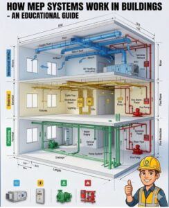
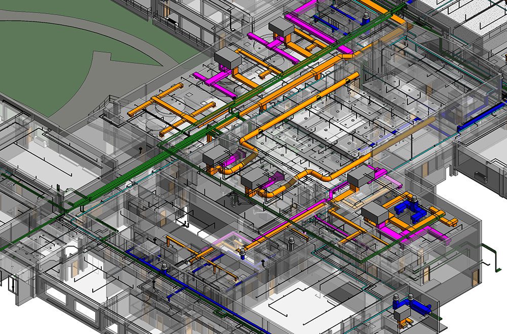
The solution is integrated MEP documentation — a single, coordinated document set in which the electrical, fire fighting, fire and life safety, and building services systems are designed and drawn together, with conflicts identified and resolved through a formal coordination review process. This is precisely the model that Varow International has applied to its projects for over four decades, delivering integrated MEP solutions in which lightning protection, fire alarm, sprinkler, emergency lighting, and evacuation systems are coordinated from concept design through to construction completion.
The Coordination Review Process
A rigorous coordination review process — documented in the form of a design review register — is the mechanism through which integration is verified.At each design stage, engineers formally review the lightning protection documentation against the fire safety documentation and the architectural emergency access drawings. They record any conflicts they identify in the design review register, assign them to a responsible engineer for resolution, and close them out with a documented design change before the project advances to the next stage.
This process creates an auditable record that demonstrates — to the building owner, the fire authority, and any future occupier — that the lightning protection system has been specifically designed not to interfere with fire safety systems or emergency access routes. In the event of a fire or lightning incident, this documentation provides the building owner and its insurers with evidence of due diligence that can be critical in resolving liability questions.
Regulatory Compliance and Authority Approvals in Pakistan
Applicable Standards and Codes
In Pakistan, lightning protection design for buildings must align with internationally recognised standards, principally IEC 62305 (Parts 1 through 4), which governs risk assessment, external and internal lightning protection, and the protection of electrical and electronic systems from LEMP. For fire safety systems, the relevant standards include NFPA 72 (National Fire Alarm and Signalling Code) and NFPA 101 (Life Safety Code), both of which building control authorities in Pakistan’s major urban centres widely reference. BS 7671 provides the framework for electrical installation design, including the wiring of fire safety systems and the specification of SPD protection.
Comprehensive lightning protection documentation demonstrates compliance with all of these standards in a coordinated manner, providing building authorities with the assurance they need to grant occupancy approvals with confidence that engineers have designed, coordinated, and documented the building’s life safety infrastructure to international best practice.
What Authorities Expect to See in Submission Documentation
When submitting lightning protection documentation for authority approval in Pakistan, building control officers and fire safety authorities increasingly expect to see not just installation drawings but a complete coordinated submission that includes the risk assessment, the SPD coordination schedule, the separation distance calculations, the cable segregation plan, and the maintenance programme. Buildings that submit this level of documentation are processed more efficiently and with fewer requests for clarification, saving time and cost in the approvals process.
Varow International has designed its project delivery process to meet this expectation as standard, structuring its documentation packages to provide authorities with every required element in a clear, professionally presented format that supports prompt and confident approval decisions.
Ongoing Maintenance Documentation and Its Life-Safety Significance
Why Maintenance Records Are Part of Lightning Protection Documentation
Lightning protection documentation does not end at practical completion. Engineers must formally record the ongoing maintenance of a lightning protection system — periodic inspection of air termination continuity, testing of earth electrode resistance, verification of SPD status, and checking of all bonding connections — in a maintenance register that the building owner retains as part of the building’s operational documentation. This ongoing record is not merely good engineering practice; in many jurisdictions and under most building insurance policies, it is a contractual requirement.
From a fire safety perspective, the maintenance documentation is significant because it provides evidence that the systems designed to protect fire safety infrastructure from lightning-induced interference remain in the condition assumed by the original design. An unmaintained lightning protection system whose earthing resistance has increased substantially or whose SPDs have degraded without replacement no longer provides the level of protection that engineers documented at handover — and the fire safety systems that engineers originally designed it to protect may consequently face interference risks that did not exist on the day of commissioning.
Integrating Lightning Protection Maintenance with Fire Safety Maintenance
Varow International consistently adopts best practice across its portfolio of completed projects by integrating the lightning protection maintenance schedule with the fire safety maintenance programme, ensuring that maintenance teams inspect both on a coordinated schedule and that engineers raise and address together any deficiencies they identify in one system that affect the other. Varow International documents this integrated approach in a combined MEP maintenance plan that it hands over to the building owner as part of the project completion documentation, providing a clear and practical framework for the building owner to safely operate the building’s life safety infrastructure over its entire service life.
Conclusion: Documentation as the Foundation of Life Safety Integration
Lightning protection and fire safety are two disciplines that the building industry has historically treated as separate specialisms with separate documentation streams. In reality, they are deeply interdependent, and the documentation that governs their design, installation, and maintenance serves as the primary mechanism through which engineers manage that interdependence. When lightning protection documentation is comprehensive, coordinated, and integrated with fire safety and emergency access documentation, it ensures that down conductors do not obstruct escape routes, that electromagnetic interference does not compromise fire alarm performance, and that SPD protection keeps fire safety panels operational through every lightning event.
For building owners, developers, and project teams in Pakistan, the message is clear: they should not treat thorough, integrated lightning protection documentation at the design stage as a cost to minimise. It is a fundamental component of life safety engineering that protects occupants, protects assets, and protects the organisations responsible for those buildings from regulatory and legal exposure.
Varow International has been delivering this level of integrated MEP engineering excellence since 1980, combining electrical services, fire fighting, and fire and life safety expertise under a single, coordinated consultancy. If you are planning a new building project or reviewing the documentation of an existing facility, contact our team to learn how we can ensure your lightning protection and fire safety systems work together without compromise.